Collision Rules
Exporting Collision Sets
Process Simulate and the RTR engine approach collision in a fundamentally different way. Process Simulate assumes no collision sets unless a user explicitly defines them. RTR on the other hand has default collision checking between all robots and the scene. For more information, please see the section on Collision Rules.
If no collision sets are active in the Collision Viewer at the time of export, the default RTR behavior will be used. Otherwise, collision rules will be generated in the export to match what has been defined in PS.
Supported Objects for Collision Rules
The Resolver engine supports 3D and 2D objects in collision rules. Any 1D objects, ITx1Dimensional, are not supported - this includes items like point clouds and PolyLines. If a user wants to have these objects included as collision objects, a 2D or 3D representation of them should be used.
Collision Rules
Collisions rules are a general term used to define how collisions between two or more objects behave. There are fundamental differences on how collisions are defined between Process Simulate and the RTR engine.
Process Simulate Default Behavior
By default, Process Simulate does not consider collisions between any objects. It is the responsibility of the user to define all collision sets. A collision will be detected if an object in the Check column is in contact with an object in the With column.
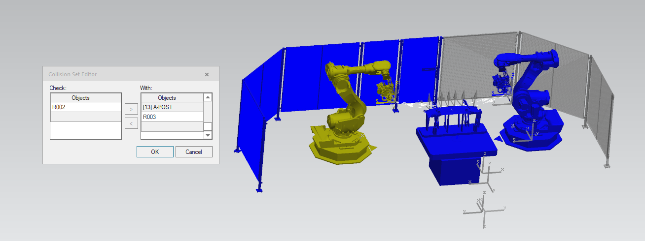
There is also a Near Miss value associated with each collision set. This acts as a warning to the user that two objects are close to each other.

More information on collision behavior in Process Simulate: https://docs.sw.siemens.com/en-US/doc/288782031/PL20231017544579710.tecnomatix_eMS.xid1015765/ToolsMenu_Options_CollisionTab
RTR Engine Default Behavior
By default, RTR's engine will detect collisions for any Robot-to-Robot and Robot-to-World contact. The mechanism to allow the user to adjust this behavior is through "disable collision rules" which is the opposite of Process Simulate behavior. Therefore, particular care is taken when converting a Process Simulate project to an RTR project.
Collision vs. Clearance
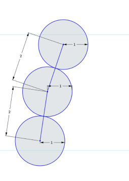
From a motion planning perspective within the RTR engine, clearances and collisions are the same concept. A collision is just clearance value of 0mm. Note that the default global clearance value used in path generation is 1mm. The clearance is checked AT MOST every 2mm on a path edge.
The RTR Engine will violate clearance (or collision) values if no alternative path is available. There is a cost associated with each solution evaluated within the engine to determine which path is best. A high cost is added to any path that violates a clearance rule, but if there is a path with only in-collision solutions available it will select one. This methodology is the most flexible for customers without forcing users to explicitly add/remove expected collisions.
As an example, collisions are expected between weld gun tips and the part. In Process Simulate, this is handled by adding ignore collision rules within the Tool Definition. If the RTR Engine did something similar, the weld tips would be ignored all the time which results in motion paths that are in collision. Instead, leaving the weld tips as collision objects, but allowing them to be in collision only if required will allow for collision free motion paths that collide only at the weld.