Exporting Study
What is exported?
Elements of a Process Simulate Study need to be exported to Resolver in order to optimally generate motion paths, interlocks, and allocate tasks. The PS ConnectorSoftware plugins, developed by RTR, that enables the export of projects from 3rd party simulation tools such as Process Simulate and Visual Components for use with Resolver. The Connector also enables... gathers the necessary CAD objects, kinematics, dynamics, operations, and targets from the PS study and automatically uploads it to Resolver upon Export.
The exporter generates a .zip file that is interpreted by Resolver. Within the .zip file, the following files are created:

project.yaml
Defines how the engine should build the workcell. It has references to all items in the objects and robot_models folders. The engine looks at this file to define how objects are positioned and mated.
queries.json
Defines the query generated from the exporter. The operations, targets, precedence constraints, etc are defined here.
metadata.json
Collects some performance and study data that is used to tailor the user experience.
objects
Stores all the .jt files of static objects that are exported.
robot_models
Stores the .jt files of robot models that is used along with kinematic defintions from the project.yaml to create virtual robot models.
Preparing for Export
Displayed Objects
Any objects (including robots) that are currently displayed will be included in the export that is sent to Resolver. It is highly recommended to blank any entities that are not necessary for motion planning in the selected operations. Blanking all unnecessary entites will improve Resolver performance and typically leads to fewer issues with unsupported objects during export.
Any robots that are not blanked and do not have an exported operation associated with them will be exported as static objects in their current pose.
Collision Sets
It is very important that collision sets are enabled and set up correctly. The defined collision sets in PS are translated into collision_rules in the project.yaml. These collision rules are used by the Resolver engine during motion planning. If the collision sets are improperly or not fully defined, the user may see unexpected motion paths in the results.

The Near Miss value in a PS Collision Set will be defined as a set_clearance rule in the project.yaml. The clearance is a "soft" rule that allows the engine to violate the clearance space if absolutely necessary. For any Collision Sets that have process points near them, it is highly recommended to use a Near Miss value < 2mm. Larger values can be used for standalone objects that the robot should have large clearances around (e.g. a pilar). If a process point is located within a large clearance value (> 2mm) the Resolver engine will spend excessive time trying to find a solution to reach that process point without violating the clearance rule. Clearance violations have an exponential effect on calculation times, so conservative values are recommended.
Supported Applications
- Spot Welding
- Riveting
- Inspection
- Point-to-point motion
- Material handling
Other applications can be supported as a service with the assistance of an RTR Application Engineer. Please enter a support ticket if you are unsure if your study is supported or would like to run a study that is outside of current tool support.
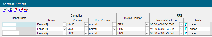
Robot Controllers
The robot controller that is selected at time of export will be what is used to perform Dynamics Calibration. Therefore, it is very important that you have the same controller selected at the time of export that you will use when inspecting results from Resolver later. The estimated cycle time and dynamics can be drastically different if, for example, MOP is selected during export and RCS is used later. Always use an RCS controller if available.
Executing Paths with MOP Motion Planner
RTR generated paths follow the same general concept that real robot controllers follow for synchronizing joints to reach the goal target at the same time. The MOP motion planner, however, does not exhibit this behavior by default. Collisions may be present in the path without properly setting the single_joint_prof parameter in the motionparameters.e file of the robot controller. From the Process Simulate motionparameters.e manual:
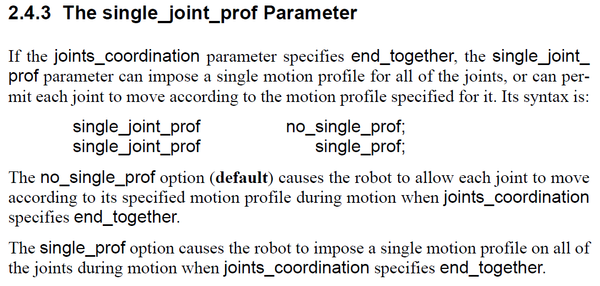
To match predicted movement by RTR and other robot manufacturers, please add the line single_joint_prof single_prof; to the motionparameters.e file.
Exporting Operations
Currently, Resolver is designed to export multiple operations or compound operations. All exported operations will use any defined links between operations to determine precedence constraints. Some rules that apply to the operations selected:
- Only targets that the robot must reach should be included. Typically, this includes only the process points, but may also include a via if the process requires a stop at that pose. New optimized vias will be generated between each target included in the operation.
- Targets in the operation must be configured. Run Auto-Teach before export if some targets are missing configs.
- Target order will be maintained in the results if Optimize Target Order is not selected.
-
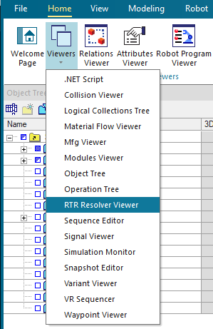
Please ensure the RTR Resolver Viewer is visible. If not, select it from the Viewers button on the ribbon.
-
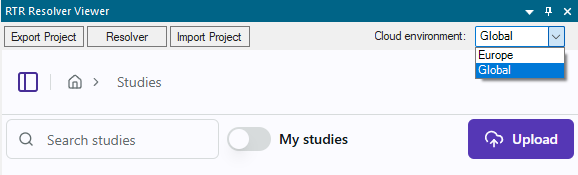
If you have not logged in, please first select the correct Cloud enviroment from the drop down menu.
- Europe: Located in Europe
- Global: Americas, APAC, all other countries.
-
In the Export section, give the export a Name (name of study)
-
Add operations or compound operations you would like to export by selecting from the
Operations Treeand then clicking the+Addbutton in the Export section. -
It is recommended to select "Calibrate robot dynamics (recommended)". If selected, the Exporter will move the robots through a series of locations using the robot controller currently selected. It will track the motions and record the dynamics of the joints. Weld guns will also be actuated at welds to capture task time at the process point. These values are embedded into the queries.json and are used by the Resolver engine to give a more accurate prediction of cycle time.
-
Select the robot OEM to specify which controller-specific smoothing options should be used. By default all of them are included. You can deselect any options that you don't want Resolver to use.
Note: The
FINEoption cannot be unchecked because it is required for interlocking at newly generated via locations. -
Click
Exportto export and automatically upload the study to the cloud.