Configure
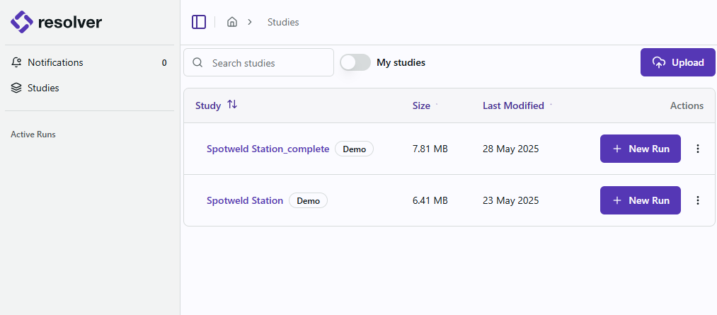
Studies
Once signed in you will be directed to the Studies page which will show all Studies that have been uploaded by your company.
Configure a Run
-
For the study that you want to start a run on, click the
+ New Runbutton. -
You will be taken to the configuration selection page. If you do not see this page, the standard Build option has been selected for you and you can skip to the next step.
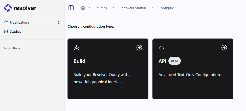
Note: The API option is an advanced workflow that requires understanding of the queries.json file as there is no UI associated with it. This option is only available as a way to enable beta features that do not yet have a UI. This procedure will follow the standard Build workflow from this point on. Please contact your RTR Applications Engineer to use the API workflow.
-
You will see a list of the sequences that were exported through the Connector. There are some additional configuration settings on this page that the user can select:
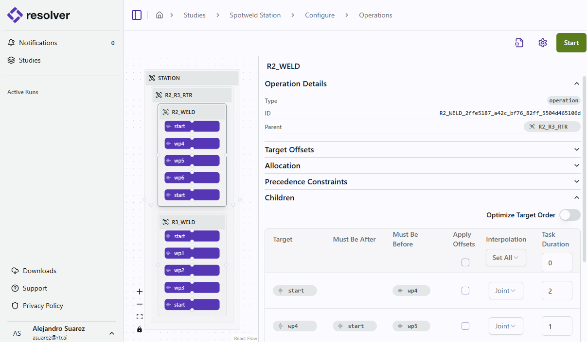
Target Offsets
Add Target Offsets to specify an X, Y, or Z offset with external axis values and apply it to as many points as you want, or all of them. Resolver will use the offsets as approach and depart points when path planning and generating interlocks.
Allocation
For any multirobot application where more than one robot can perform the same task, let Resolver know which robots are allowed to be considered for that operation. Resolver will consider all robots selected and evaluate reachability, paths, and interlocks that result in the optimal target-to-robot allocation. Please note that using this feature expands the number of possible solutions and Resolver should be run longer.
Precedence Constraints
Displays the actions or operations that must start after or be completed before the selected operation. Precedence constraints are generated by the Connector based on information from the simulation tool. See
Children
If a parent or compound operation is selected, then all the children operations are listed. If an operation with targets is selected, the list of all targets for that particular operation is shown.
Interpolation
The Interpolation column controls how the EngineThe engine (or Resolver Engine) refers to the core algorithm that is running in Resolver that takes a study and a query; generates collision free motion paths, interlocks, and task allocations; and pr... interpolates motion paths to and from process points. The following options are available:
-
Joint: The robot moves each joint along the shortest path in joint space to reach the target. This is the fastest interpolation mode and is the default. Joint moves can appear less predictable to humans because the TCP does not follow a straight line, but they maximize cycle time performance.
-
Linear: The robot moves the TCP along a straight line in Cartesian space between waypoints. Linear moves are slower than joint moves but produce predictable, human-readable paths that are easier to touch up during commissioning. Resolver will fall back to joint interpolation on any linear-specified motions that fail to generate due to joint limitations or singularity detection.
-
Hybrid: Intelligently switches between joint and linear interpolation based on proximity to process points. This option is enabled by a feature flag for the org in Resolver — if you expect to see it and do not, contact RTR Support.
-
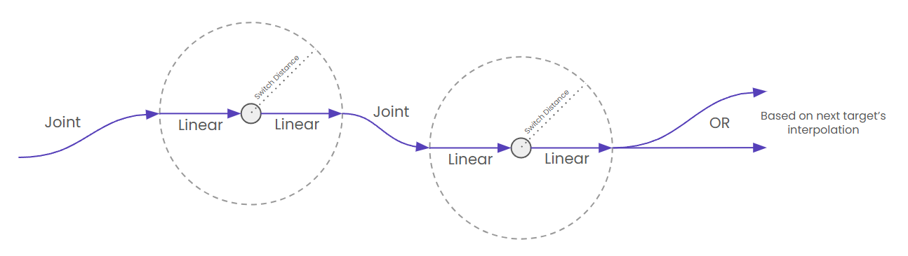
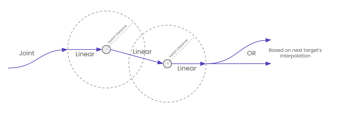
What is Hybrid Interpolation?
Hybrid interpolation is a trajectory planning mode that intelligently switches between joint and linear interpolation based on proximity to target waypoints. It combines high-speed joint motion at far distances with the control and human-preference of linear motion near process points.
The EngineThe engine (or Resolver Engine) refers to the core algorithm that is running in Resolver that takes a study and a query; generates collision free motion paths, interlocks, and task allocations; and pr... switches interpolation type based on whether paths are being generated outside or inside a zone around the process point:
- Outside switch zone: Uses fastest-path Joint interpolation for maximum cycle time performance.
- Inside switch zone: Switches to Linear interpolation for controlled motion that is easier for humans to touch up during commissioning.
The distance threshold that determines when to transition between modes is called the Switch Distance.
noteResolver will fall back to joint interpolation on any linear-specified motions that fail to generate due to joint limitations or singularity detection. This is true for all planned linear moves regardless of the hybrid designation.
-
Hybrid Interpolation for Spot Welding
Hybrid interpolation behavior depends on the spacing between spot weld points:
-
Non-overlapping Switch Distances: When process points are spaced far enough apart that their switch distance zones do not overlap, the system will use Joint interpolation for the transit segments if it results in a faster path. This allows the robot to take advantage of joint interpolation's speed benefits during longer transit motions between process points.
-
Overlapping Switch Distances: When process points are close enough that their switch distance bubbles overlap, the interpolation will remain Linear throughout the entire via motion. This ensures consistent, precise motion when process points are in close proximity, maintaining the benefits of linear interpolation across the entire path segment.
-
-
Hybrid Parameters
After selecting the Hybrid option, the following parameters can be adjusted:
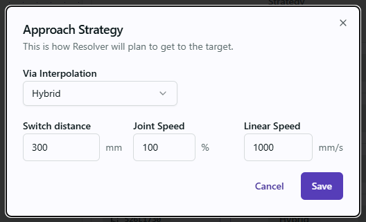
- Switch Distance: The radius of the zone around the process point where the EngineThe engine (or Resolver Engine) refers to the core algorithm that is running in Resolver that takes a study and a query; generates collision free motion paths, interlocks, and task allocations; and pr... will switch from high-speed joint moves to speed-limited linear moves.
- Joint Speed: Max speed used for generated vias outside the switch zone. Highly recommended to leave at 100%.
- Linear Speed: Max speed used for generated vias inside the switch zone.
-
Optimize Target Order
The engine will optimize the sequence by allowing the reordering of targets, except for the first and last targets, which remain fixed as the required start and end points. All other targets in between may be rearranged if the engine determines that an alternative order improves the cycle time.
Task Duration
The task time is analogous to a "wait" time at each target. For spot welding, this should be the amount of time a spot weld takes to happen. Users can manually adjust the Task Duration values for any target in the sequence if desired.
-
-
Select ⚙ View Query Settings in the top right corner of the page to modify settings. The following query settings are available:
Motion Settings
Avoid Other Robots' Home Positions
This setting ensures that the motion paths generated for one robot do not intersect with the first and last targets ("Home" targets) of other robots. However, if no viable path exists that maintains this rule, results may include rule violations, collisions, or fail to find a solution. Therefore, it is crucial that users verify the Home targets are well outside the motion path of the other robots if enabling this option.
Enable Smoothing
Use this setting to allow generated via points to use a non-zero smoothing value. If enabled, the engine will attempt to use one of the values in the
smoothing_tablessection of the queries.json file. The engine will optimize via count and smoothing values to give the best cycle time. The targets in the sequence list (process points) will not have these smoothing values applied to them.End Conditions
Convergence
These two settings allow a user to configure when the engine has reached convergence on a solution. The values should allow the engine to attempt to improve the current solution for an adequate amount of time without running indefinitely. Essentially, there is a "timer" that starts when the run starts. The behavior of this timer can be adjusted with the following settings.
- Improvement Threshold (s): The minimum improvement in cycle time required to be considered making progress. If this threshold is exceeded, the "timer" is reset to zero and starts again.
- Time Threshold (s): The max limit for the "timer". Once this value is reached, the run is considered to have converged to a solution and the run will automatically complete.
Elapsed Time
- Time Threshold (s): A maximum amount of time the run can last regardless of the convergence timer.
-
After configuration is complete, select the Start button in the upper right corner. At this point, a license will be checked out and a server will be provisioned in the cloud.